MotoCache1
Chief Droid Scientist
- Joined
- Jun 30, 2010
- Messages
- 530
- Reaction score
- 1
Sorry I fell off the face of the Earth for an extended period. Work is just too busy to have much time for playing - and while I've had a tiny amount of time to hack on some things, I've just not had the cycles to be active on the forums.
That said, one of the things I did tackle awhile back was the Motorola Factory Cable. Most people have never heard of a Motorola Factory Cable, much less seen one, held one, or have a chance to figure out how it works. Having had the rare opportunity to do all of the above I'm taking a little time to post up the schematic so you can make your own, as well as tell you why you might want to.
As usual (for me), this will be lengthy, so go get a some coffee, or a Red Bull, or whatever lets you get through one of my write-ups.
Problem we're trying to solve
Programming (flashing) your phone requires a sufficiently charged battery. If the phone detects (rightly or wrongly) that your battery doesn't have enough charge, it won't allow you to attempt flashing. This is to protect you from yourself. If the phone were to lose power in mid-flash might permanently brick the phone.
The problem is, sometimes you flash your phone and foul it up such that the phone can't boot up far enough to allow charging to take place. During successive flashing attempts, you may run down the battery and get to the point where you no longer have enough of a charge to attempt a flash. Or, the phone may simply think that your battery is near dead (even if it's not) and refuse to allow you to flash it. Having a spare (charged) battery is always a good plan, as is having a desktop charger so you can charge a battery without having a functioning phone. But even these won't help you if your phone is fouled up such that even a full battery is seen as near-dead.
The "Factory Cable"
It seems intuitive that they probably don't have fully charged batteries lying around the factory to put in the phones when they get their initial programming. This would un-necessarily complicate the manufacturing process. As it turns out, when the factory programs the phone, they don't need to have a battery in the phone at all. Enter the "Factory Cable".
Pretty much every Motorola Phone that I know of (that has a Mini-B or a Micro-B USB port) can be powered up and programmed even without a battery in it, using the Motorola Factory Cable. The problem is (as previously mentioned) nobody has one, has seen one, or even knows what one is -- until now.
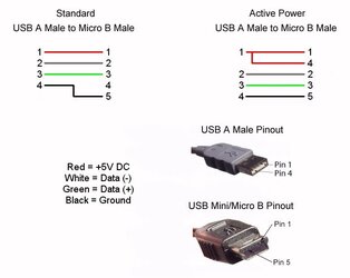
Turns out the Factory Cable is actually pretty simple. Normally pin 4 of the Mini/Micro B connector has nothing connected to it. With the Factory Cable, pin 4 of the Mini/Micro connector is tied to pin 1 which is +5V DC. This is sort of the polar opposite (literally) of most USB "charging cables" (cables designated specifically for charging phones that are snooty about what can and can't charge them). Most "charging cables" tie pin 4 of the Mini/Micro connector to ground and this is what signals the phone that this is a special charging cable and it is allowed to charge. Sometimes there are resistors in this circuit to specifically identify the manufacturer's charging cable, etc. -- but I digress.
So the Factory Cable has +5V DC on pin 4 of the Mini/Micro connector. That alone isn't enough to make the Factory Cable fire up the phone. If you take a Factory Cable, connect it to your phone, and then plug it into a USB cube (you know, the little wall wart that you plug into the wall and it has a USB port on it for charging), nothing will happen. The reason is that the Factory Cable is for flashing, not charging. In order to do anything the phone needs to detect that there is a computer at the other end of the data lines -- then it will fire right up -- even with no battery installed.
What's very interesting is that the phone definitely knows that it is not in the presence of mere mortals when you use a Factory Cable. The phone knows it is in the presence of Moto gods as it boot differently than normal. Some phones like the Motorola Napoleon actually come right out and say "Factory Cable Connected". Other phones will boot straight to the bootloader for flashing. The various Droids appear to boot normally until you notice that there is no USB connected indicator at the top (once the OS is up) and that the host computer doesn't register all the usual devices. Instead the host computer only registers the bare minimum interfaces needed for RadioComm, RSD Lite, etc. to be able to talk to the phone. This in and of itself simplifies things as you don't have to monkey with setting the phone to the right mode (e.g. "PC Mode") -- it is automatically in the right mode for flashing.
Another interesting thing that is allegedly possible with the Factory Cable is that with the battery removed, it is possible to access some diagnostic pads on the main board of the phone, that when shorted (before connecting the Factory Cable) will boot the phone in a special recovery mode to help recover bricked phones. I say "allegedly" because thus far we've not had much luck with this, and our information is that it may only apply to unsecured phones anyway -- not secured consumer phones. Running around shorting things randomly inside your phone is a very bad idea unless you are willing to risk the phone, your computer, or both -- but sometimes things must die in the name of science -- but again I digress.
By now you are probably saying "OK, fine Moto, enough rambling, how the hell do I make one of these things already?"
In a way, I've already told you. You simply need to tie pin 4 of the Mini/Micro end to pin 1 (+5V DC) and you're all set. Unfortunately that is much easier said than done. The big wrinkle is that since in 99% of cables pin 4 on the Micro B is unused, the cables only have 4 wires in them and pin 4 has no wire connected at all.
When attempting to replicate the Factory Cable I had the pleasure of examining, I took a regular Motorola USB A to Micro B cable (just like the one that comes with your phone) and cut the Micro B end off it. Then I took a old cable that had a Mini B male connector on it and took a razor blade and removed all the injection molded rubber from the connector (very carefully) to get down to the raw connector. By the way, I chose to work on a Mini B instead of a Micro B just because for testing purposes it is a little easier to isolate the pins in a Mini than a Micro). Anyway, I was disappointed to find that not only was there no wire connected to pin 4 (as expected), but the actual pin for pin 4 had been clipped off as well (foiling my plans of simply soldering a wire to it). Also, in my rubber removal process I damaged the jackets on the wires that were soldered to the connector a little, so, fearing the possibility of a short on those bare wires, I de-soldered them all with the intent to solder on new ones. That was a poor choice by the way.
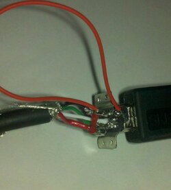
Not to be defeated by the snipped off pin for pin 4 (on the Mini B connector) I set the temperature of the solder station to about 700 degrees Fahrenheit and melted away some of the plastic on the connector to try to expose at least a little of the pin so I could get a solder blob to stick to it. After some effort I succeeded in getting a little solder to stick to the now barely exposed pin end. Then I set about resoldering all the wires back to the connector with freshly stripped and tinned ends, and adding a jumper between pin 1 and pin 4 to get the +5V DC where it was needed.
The end result looked like this:

Then I took that monstrosity and checked it with a continuity meter to make sure none of the various solder joints was touching another. Soldering that tiny tiny stuff is no treat. You really need 3 or 4 hands. I highly suggest one of those little helpers that has adjustable arms and little alligator clips on the arms that helps hold things where they need to be so you can use your hands for soldering.
Anyway, having passed continuity checks, I plugged it into a Mini to Micro adapter and then plugged that into a Motorola Napoleon to see what would happen.
Fortunately nothing caught on fire or blew up and a moment later the Nap fired up and said "Factory Cable Connected". I'm not sure I've been that happy since I picked my first lock.
Various and sundry playing ensued after this little triumph. My Frankenstein cable did everything the genuine Factory Cable did, and I was satisfied. The thing is, my Frankenstein cable is a pretty scary piece of garbage. I wouldn't trust it for routine use because it is just begging for something to touch something and then destroy a phone or the computer. When you look at what we're doing, we're putting +5V DC on pin 4, and only 17 thousandths of an inch away is ground on pin 5. Should pin 4 and pin 5 ever be allowed to "visit" each other, it will be a direct short of your USB port and at a minimum will destroy that USB port in your computer -- if it doesn't fry your whole motherboard (and if the phone was connected at the time, so much worse the mess).
So, something a little more durable and safe was in order. Now, there are plenty of different ways to go about this -- each with their good points and bad. I think an ideal cable will be one where pin 1 and pin 4 of the Mini/Micro B have their own wire all the way back to the USB A end. You could cheat and do a jumper at the Mini B end, but then you've got one wire feeding +5V DC to two pins and the engineer in me doesn't like that. The best way to build one of these would be to buy a USB A male connector and a USB Micro B male connector (or Mini B but then you need to use a Mini to Micro adapter), and some shielded 5 wire cable, and wire it up as per the schematic below. This is completely do-able. You can get just about any cable and connector you like from Digi-key (or any number of places) and have at it. You could even make a Frankenstein cable like my first effort, but honestly that is just begging for trouble.
I gave the pinout to my TBH cohorts and a vendor was contracted to custom make a small run of these cables. You absolutely do not need to purchase one of these from them as you can certainly make your own if you are handy with a soldering iron and are careful. That said, even if you are going to make your own, you should check out the text on the product page as it has some important tips and warnings about usage of the cable. This page is the only page where I'm posting the "how to" and that page is the only place where I am maintaining any usage tips or warnings that I may think of -- so not having to do repetitive edits in two places makes my life easier.
Important Note: since I have no control over your ability to build this cable, the quality of your soldering, etc., obviously I take no responsibility for your usage of this information. If you do this wrong, you could destroy your phone, your computer, or both. This cable is definitely a cool tool to have, and it is the only way I do flashing anymore, but you have to heed the warnings that I linked to earlier and even then, you're doing something Motorola probably didn't intend anybody outside of their divine provenance to do, so you're on your own.
Anyway, warnings aside, here's the schematic (the "Active Power" schematic is the one for the "Factory Cable"):

Good luck and have fun! I had a blast figuring this out.
[Edited to add: See this post for a solution to the "missing pin 4" obstacle.]
That said, one of the things I did tackle awhile back was the Motorola Factory Cable. Most people have never heard of a Motorola Factory Cable, much less seen one, held one, or have a chance to figure out how it works. Having had the rare opportunity to do all of the above I'm taking a little time to post up the schematic so you can make your own, as well as tell you why you might want to.
As usual (for me), this will be lengthy, so go get a some coffee, or a Red Bull, or whatever lets you get through one of my write-ups.
Problem we're trying to solve
Programming (flashing) your phone requires a sufficiently charged battery. If the phone detects (rightly or wrongly) that your battery doesn't have enough charge, it won't allow you to attempt flashing. This is to protect you from yourself. If the phone were to lose power in mid-flash might permanently brick the phone.
The problem is, sometimes you flash your phone and foul it up such that the phone can't boot up far enough to allow charging to take place. During successive flashing attempts, you may run down the battery and get to the point where you no longer have enough of a charge to attempt a flash. Or, the phone may simply think that your battery is near dead (even if it's not) and refuse to allow you to flash it. Having a spare (charged) battery is always a good plan, as is having a desktop charger so you can charge a battery without having a functioning phone. But even these won't help you if your phone is fouled up such that even a full battery is seen as near-dead.
The "Factory Cable"
It seems intuitive that they probably don't have fully charged batteries lying around the factory to put in the phones when they get their initial programming. This would un-necessarily complicate the manufacturing process. As it turns out, when the factory programs the phone, they don't need to have a battery in the phone at all. Enter the "Factory Cable".
Pretty much every Motorola Phone that I know of (that has a Mini-B or a Micro-B USB port) can be powered up and programmed even without a battery in it, using the Motorola Factory Cable. The problem is (as previously mentioned) nobody has one, has seen one, or even knows what one is -- until now.
Turns out the Factory Cable is actually pretty simple. Normally pin 4 of the Mini/Micro B connector has nothing connected to it. With the Factory Cable, pin 4 of the Mini/Micro connector is tied to pin 1 which is +5V DC. This is sort of the polar opposite (literally) of most USB "charging cables" (cables designated specifically for charging phones that are snooty about what can and can't charge them). Most "charging cables" tie pin 4 of the Mini/Micro connector to ground and this is what signals the phone that this is a special charging cable and it is allowed to charge. Sometimes there are resistors in this circuit to specifically identify the manufacturer's charging cable, etc. -- but I digress.
So the Factory Cable has +5V DC on pin 4 of the Mini/Micro connector. That alone isn't enough to make the Factory Cable fire up the phone. If you take a Factory Cable, connect it to your phone, and then plug it into a USB cube (you know, the little wall wart that you plug into the wall and it has a USB port on it for charging), nothing will happen. The reason is that the Factory Cable is for flashing, not charging. In order to do anything the phone needs to detect that there is a computer at the other end of the data lines -- then it will fire right up -- even with no battery installed.
What's very interesting is that the phone definitely knows that it is not in the presence of mere mortals when you use a Factory Cable. The phone knows it is in the presence of Moto gods as it boot differently than normal. Some phones like the Motorola Napoleon actually come right out and say "Factory Cable Connected". Other phones will boot straight to the bootloader for flashing. The various Droids appear to boot normally until you notice that there is no USB connected indicator at the top (once the OS is up) and that the host computer doesn't register all the usual devices. Instead the host computer only registers the bare minimum interfaces needed for RadioComm, RSD Lite, etc. to be able to talk to the phone. This in and of itself simplifies things as you don't have to monkey with setting the phone to the right mode (e.g. "PC Mode") -- it is automatically in the right mode for flashing.
Another interesting thing that is allegedly possible with the Factory Cable is that with the battery removed, it is possible to access some diagnostic pads on the main board of the phone, that when shorted (before connecting the Factory Cable) will boot the phone in a special recovery mode to help recover bricked phones. I say "allegedly" because thus far we've not had much luck with this, and our information is that it may only apply to unsecured phones anyway -- not secured consumer phones. Running around shorting things randomly inside your phone is a very bad idea unless you are willing to risk the phone, your computer, or both -- but sometimes things must die in the name of science -- but again I digress.
By now you are probably saying "OK, fine Moto, enough rambling, how the hell do I make one of these things already?"
In a way, I've already told you. You simply need to tie pin 4 of the Mini/Micro end to pin 1 (+5V DC) and you're all set. Unfortunately that is much easier said than done. The big wrinkle is that since in 99% of cables pin 4 on the Micro B is unused, the cables only have 4 wires in them and pin 4 has no wire connected at all.
When attempting to replicate the Factory Cable I had the pleasure of examining, I took a regular Motorola USB A to Micro B cable (just like the one that comes with your phone) and cut the Micro B end off it. Then I took a old cable that had a Mini B male connector on it and took a razor blade and removed all the injection molded rubber from the connector (very carefully) to get down to the raw connector. By the way, I chose to work on a Mini B instead of a Micro B just because for testing purposes it is a little easier to isolate the pins in a Mini than a Micro). Anyway, I was disappointed to find that not only was there no wire connected to pin 4 (as expected), but the actual pin for pin 4 had been clipped off as well (foiling my plans of simply soldering a wire to it). Also, in my rubber removal process I damaged the jackets on the wires that were soldered to the connector a little, so, fearing the possibility of a short on those bare wires, I de-soldered them all with the intent to solder on new ones. That was a poor choice by the way.
Not to be defeated by the snipped off pin for pin 4 (on the Mini B connector) I set the temperature of the solder station to about 700 degrees Fahrenheit and melted away some of the plastic on the connector to try to expose at least a little of the pin so I could get a solder blob to stick to it. After some effort I succeeded in getting a little solder to stick to the now barely exposed pin end. Then I set about resoldering all the wires back to the connector with freshly stripped and tinned ends, and adding a jumper between pin 1 and pin 4 to get the +5V DC where it was needed.
The end result looked like this:
Then I took that monstrosity and checked it with a continuity meter to make sure none of the various solder joints was touching another. Soldering that tiny tiny stuff is no treat. You really need 3 or 4 hands. I highly suggest one of those little helpers that has adjustable arms and little alligator clips on the arms that helps hold things where they need to be so you can use your hands for soldering.
Anyway, having passed continuity checks, I plugged it into a Mini to Micro adapter and then plugged that into a Motorola Napoleon to see what would happen.
Fortunately nothing caught on fire or blew up and a moment later the Nap fired up and said "Factory Cable Connected". I'm not sure I've been that happy since I picked my first lock.
Various and sundry playing ensued after this little triumph. My Frankenstein cable did everything the genuine Factory Cable did, and I was satisfied. The thing is, my Frankenstein cable is a pretty scary piece of garbage. I wouldn't trust it for routine use because it is just begging for something to touch something and then destroy a phone or the computer. When you look at what we're doing, we're putting +5V DC on pin 4, and only 17 thousandths of an inch away is ground on pin 5. Should pin 4 and pin 5 ever be allowed to "visit" each other, it will be a direct short of your USB port and at a minimum will destroy that USB port in your computer -- if it doesn't fry your whole motherboard (and if the phone was connected at the time, so much worse the mess).
So, something a little more durable and safe was in order. Now, there are plenty of different ways to go about this -- each with their good points and bad. I think an ideal cable will be one where pin 1 and pin 4 of the Mini/Micro B have their own wire all the way back to the USB A end. You could cheat and do a jumper at the Mini B end, but then you've got one wire feeding +5V DC to two pins and the engineer in me doesn't like that. The best way to build one of these would be to buy a USB A male connector and a USB Micro B male connector (or Mini B but then you need to use a Mini to Micro adapter), and some shielded 5 wire cable, and wire it up as per the schematic below. This is completely do-able. You can get just about any cable and connector you like from Digi-key (or any number of places) and have at it. You could even make a Frankenstein cable like my first effort, but honestly that is just begging for trouble.
I gave the pinout to my TBH cohorts and a vendor was contracted to custom make a small run of these cables. You absolutely do not need to purchase one of these from them as you can certainly make your own if you are handy with a soldering iron and are careful. That said, even if you are going to make your own, you should check out the text on the product page as it has some important tips and warnings about usage of the cable. This page is the only page where I'm posting the "how to" and that page is the only place where I am maintaining any usage tips or warnings that I may think of -- so not having to do repetitive edits in two places makes my life easier.
Important Note: since I have no control over your ability to build this cable, the quality of your soldering, etc., obviously I take no responsibility for your usage of this information. If you do this wrong, you could destroy your phone, your computer, or both. This cable is definitely a cool tool to have, and it is the only way I do flashing anymore, but you have to heed the warnings that I linked to earlier and even then, you're doing something Motorola probably didn't intend anybody outside of their divine provenance to do, so you're on your own.
Anyway, warnings aside, here's the schematic (the "Active Power" schematic is the one for the "Factory Cable"):
Good luck and have fun! I had a blast figuring this out.
[Edited to add: See this post for a solution to the "missing pin 4" obstacle.]